Starting with version 1.0.4 the linux versions of Repetier-Server can access GPIO pins directly from the interface. This allows it to change a output pin to trigger a relay for example. But you can also check a input for a signal change and trigger some actions. This would be required to add a server controlled filament sonsor or to have some extra buttons that trigger quick functions like an emergency button.
If you think this is something for you, make sure your electronic knowledge is good enough for the task. You will be connecting and configuring new electronics and errors can lead to physical damage of your computer. You do this on your own risk, so don’t tell me I did not warn you.
Now for the brave, the page to control these pins is in Global Settings->GPIO Pins. At the beginning the list is empty and you can add new entries with a dialog box at the bottom. You select one of the five types and give it a name. If you want to use it also in g-code the name should NOT contain whitespaces! The name for the menu can be selected later on. Once added the editor opens. The contents differs and will be described in the next sections.
A fully configured setup might look like this test setup.
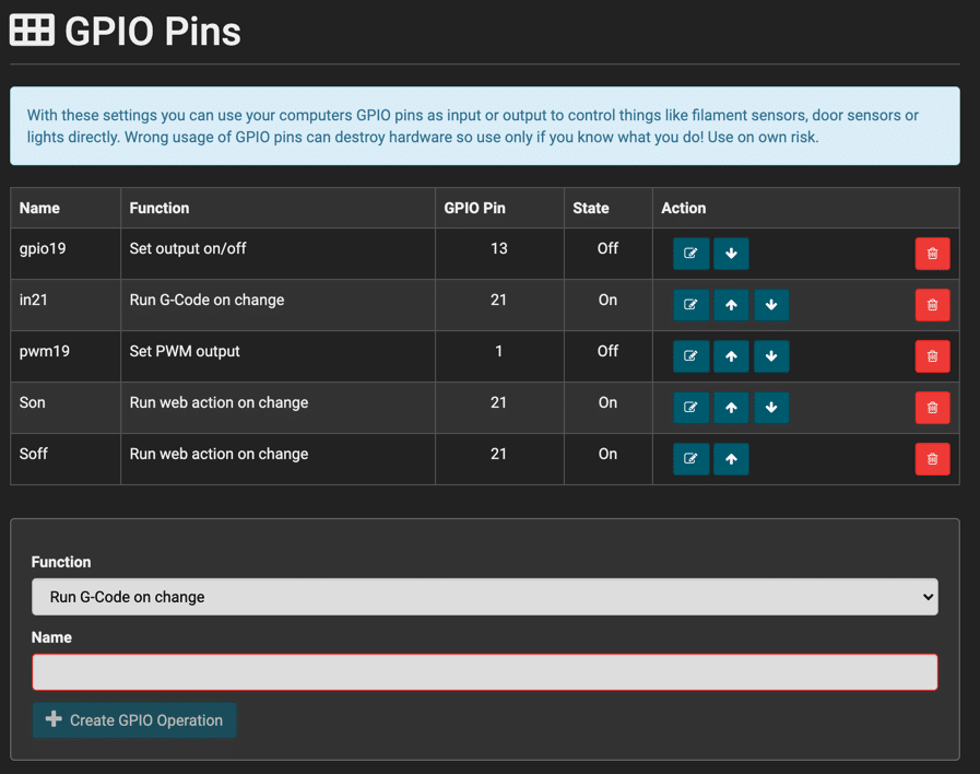
In the image above you see the table with all entries. Name is the official name you would also use for @gpio server command. Function describes what it does. GPIO Pin is the pin number. Raspberry PI users should watch out with the numbering scheme. There are several numberings in use in the available tutorials. Often they use wiringPi numbering, but we use the numbers as assigned by linux which is in tutorial normally called BCM numbering based on the chipset used. For pwm outputs it is the pwm channel and not a pin number!
Starting with pi 4 there is another issue you need to watch out for the pin numbers. What we use is the linux numbering of the pins and with multiple gpio capable chips, they can not all start with 0. Unfortunately the mostly used gpio pins of the processor it self are offset. The best is login to linux and query linux for the pin number.
cat /sys/kernel/debug/gpio
# Response is something like this
gpiochip0: GPIOs 0-57, parent: platform/fe200000.gpio, pinctrl-bcm2711:
 gpio-0   (ID_SDA              )
 gpio-1   (ID_SCL              )
 gpio-2   (GPIO2               )
 gpio-3   (GPIO3               )
 gpio-4   (GPIO4               )
 gpio-5   (GPIO5               )
 gpio-6   (GPIO6               )
 gpio-7   (GPIO7               )
 gpio-8   (GPIO8               )
 gpio-9   (GPIO9               )
 gpio-10  (GPIO10              )
 gpio-11  (GPIO11              )
 gpio-12  (GPIO12              )
 gpio-13  (GPIO13              )
 gpio-14  (GPIO14              )
 gpio-15  (GPIO15              )
 gpio-16  (GPIO16              )
 gpio-17  (GPIO17              )
 gpio-18  (GPIO18              )
 gpio-19  (GPIO19              )
 gpio-20  (GPIO20              )
 gpio-21  (GPIO21              )
 gpio-22  (GPIO22              |sysfs               ) in  lo
 gpio-23  (GPIO23              )
 gpio-24  (GPIO24              )
 gpio-25  (GPIO25              )
 gpio-26  (GPIO26              )
 gpio-27  (GPIO27              )
 gpio-28  (RGMII_MDIO          )
 gpio-29  (RGMIO_MDC           )
 gpio-30  (CTS0                )
 gpio-31  (RTS0                )
 gpio-32  (TXD0                )
 gpio-33  (RXD0                )
 gpio-34  (SD1_CLK             )
 gpio-35  (SD1_CMD             )
 gpio-36  (SD1_DATA0           )
 gpio-37  (SD1_DATA1           )
 gpio-38  (SD1_DATA2           )
 gpio-39  (SD1_DATA3           )
 gpio-40  (PWM0_MISO           )
 gpio-41  (PWM1_MOSI           )
 gpio-42  (STATUS_LED_G_CLK    |ACT                 ) out lo
 gpio-43  (SPIFLASH_CE_N       )
 gpio-44  (SDA0                )
 gpio-45  (SCL0                )
 gpio-46  (RGMII_RXCLK         )
 gpio-47  (RGMII_RXCTL         )
 gpio-48  (RGMII_RXD0          )
 gpio-49  (RGMII_RXD1          )
 gpio-50  (RGMII_RXD2          )
 gpio-51  (RGMII_RXD3          )
 gpio-52  (RGMII_TXCLK         )
 gpio-53  (RGMII_TXCTL         )
 gpio-54  (RGMII_TXD0          )
 gpio-55  (RGMII_TXD1          )
 gpio-56  (RGMII_TXD2          )
 gpio-57  (RGMII_TXD3          )

gpiochip2: GPIOs 502-503, parent: i2c/10-0045, 7inch-touchscreen-p, can sleep:
 gpio-502 (                    |100000002.reg_bridge) out ?
 gpio-503 (                    |reset               ) out ?   ACTIVE LOW

gpiochip1: GPIOs 504-511, parent: platform/soc:firmware:gpio, raspberrypi-exp-gpio, can sleep:
 gpio-504 (BT_ON               |shutdown            ) out hi
 gpio-505 (WL_ON               )
 gpio-506 (PWR_LED_OFF         |PWR                 ) out lo ACTIVE LOW
 gpio-507 (GLOBAL_RESET        )
 gpio-508 (VDD_SD_IO_SEL       |vdd-sd-io           ) out hi
 gpio-509 (CAM_GPIO            |cam1_regulator      ) out hi
 gpio-510 (SD_PWR_ON           |regulator-sd-vcc    ) out hi
 gpio-511 (SD_OC_N             )
Here on a pi 3 the gpio-xx values are identical with GPIOxx names, on others they can differ. So use the number from gpio- with the description matching your pin.
Set output on/off
This is the most basic output function. It allows you to control a pins output either by @gpio server command or by toggling it in the menu. Most important thing when using a output pin is, to not draw more current then the pin can deliver. That is normally not much. If you draw more the best that can happen is that just that output dies. Add a 330 Ohm resistor after the output and you are normally safe. Still enough for a simple led. For a relais you need more electronic, so I leave that to the experts.
So lets look at the editor:
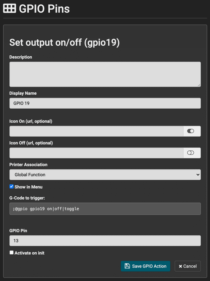
Description is for your internal use. Make notes so you know what you wanted or what to do to recreate it.
Display Name is the name that you will see in the menu for the function.
Next you have Icon On and Icon Off. Both are optional and should be svg graphics indicating device is on or off. If omitted you get a defazlt switch icon from us.
Printer Association controls in which menu the function will be put. It is either Global Function or one of your 3d printer names. The Show in Menu checkbox controls, if you will see it in a menu at all. If not it can only be called as server command.
Next you see the correct server command to enable, disable or toggle the pins output.
GPIO Pin is the physical pin with numbering linux uses. For raspberry pi users this means the BCM numbering scheme.
Last checkbox Activate on Init can be set, if you want the signal to be on when server starts. Otherwise it will be off at startup.
Set PWM Output
This is a bit more complex. A pwm output does change the output signal very quickly. The percentage between on and off can be defined to allow e.g. a dimmed light. The main problem is that you can not simply say which pin to use. Instead you assign it to a channel. Which channel maps to which pin depends on your linux configuration. For raspberry pi you even have to enable this feature. Normally pwm is used for audio output. For raspberry pi you edit /boot/config.txt to enable pwm for pins and also to configure which channel maps to which pin. E.g. adding
dtoverlay=pwm-2chan,pin=12,func=4,pin2=13,func2=4
From the overlay description:
| Name: | pwm-2chan | ||||||||||
| Info: | Configures both PWM channels Legal pin,function combinations for each channel: PWM0: 12,4(Alt0) 18,2(Alt5) 40,4(Alt0) 52,5(Alt1) PWM1: 13,4(Alt0) 19,2(Alt5) 41,4(Alt0) 45,4(Alt0) 53,5(Alt1) N.B.:
|
||||||||||
| Load: | dtoverlay=pwm-2chan,<param>=<val> | ||||||||||
| Params: |
|
The dialog for pwm looks like this:
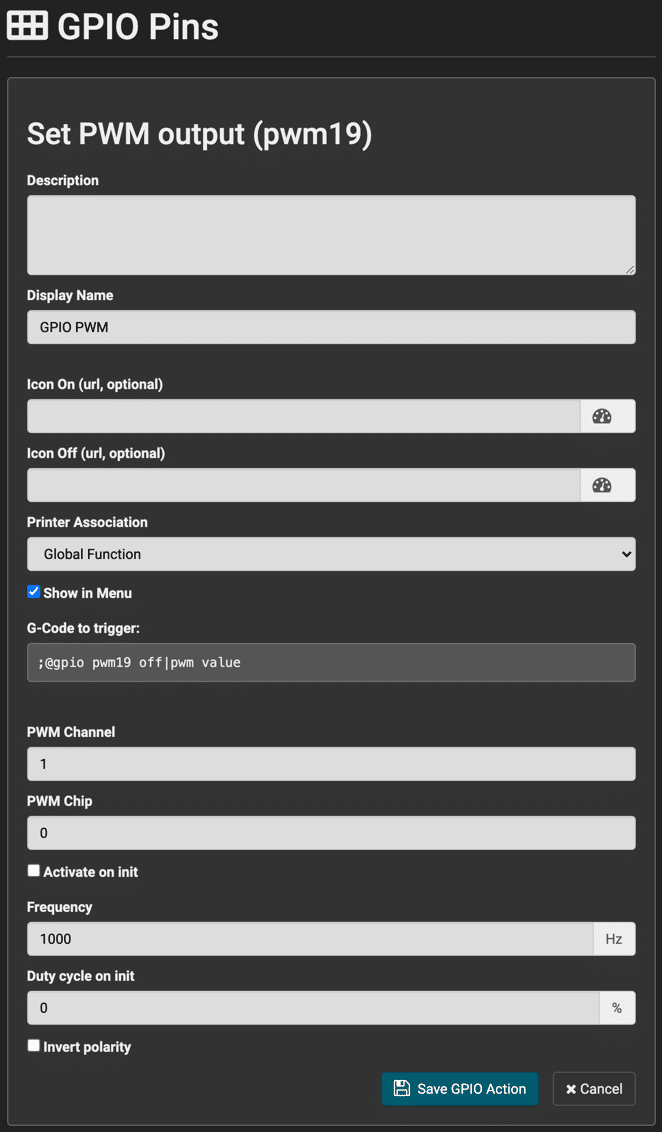
The main difference is that you need to set the PWM Channel and PWM Chip instead of a pin. Chip is normally 0. Frequency is the PWM frequency while duty cycle defines how much on it is. Value is in percent. With invert polarity you can make 0 map to 100% on and vice versa.
In the menu you get a knob to select power when selected. In the server command you can still use on and off for 100 and 0% but also enter the percentage directly.
Run G-Code on change
The last 3 selections are very similar. They only differ in the action taken on signal change. Here we take a GPIO pin as input signal and execute an action on a switch from low to high or high to low. The dialog looks like this:
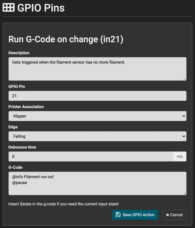
GPIO Pin is the input signal pin. Also some chips can define a pull-up or pull-down resistor internally, we can not do this. So it is best to a physical resistor to pull signal explicitly if required. Normally a resistor between 1k and 10k should make no problems.
Edge defines when to trigger and can be Falling (High to Low), Rising (Low to High) or Both.
Debounce time tells how long the signal must be stable to trigger. Especially important on cheap buttons that change signal at the beginning.
Last is the G-Code to execute on the selected printer. In this case we assume an external filament sensor that the server monitors. We make a info dialog pop up informing what the problem is and then pause the printer. Make sure the pause script moves away from the print.
Run web action on change
Same as previous input handling. The only difference is that you select from a dropdown list the web action that should be executed. Of course it must be defined previously in the Web Action tab.
Run external command on change
Same as the last 2 inputs. Here you select one the defined external action defined in extcommands.xml.
Raspberry Pi
From those using the GPIO pins I guess 99% will be using one of the Raspberry Pi models available. All later models share the same 40 pin GPIO header that is explicitly meant to extend the board. Apart from some 5V, 3.3V and ground pins, all can be used for input and output operations. If you can, spare those that can also be used as special functions like I2C or serial communication. If you want to use those, make sure no driver or software is using them.
Also already stated here I repeat that online tutorials use two different naming schemes. wiringPi and BCM. Here you need the BCM scheme as shown in the image below:

When you login via ssh you can check the pins and their configuration:
gpio readall
You can also use gpio to configure and change pins. Note that when you refer a pin you need -g option to tell gpio to use BCM numbering.